Frequency Vs Impedance for Bypass (Decoupling) Capacitors
In an Ideal Capacitor, the impedance would continuously drop as the frequency goes up. As a result of ESL and ESR however, the impedance of a real capacitor rises with frequency after reaching a minumum:
The image below shows the Frequency characteristics of the Murata GRM15 Series of capacitor: (1)(2)
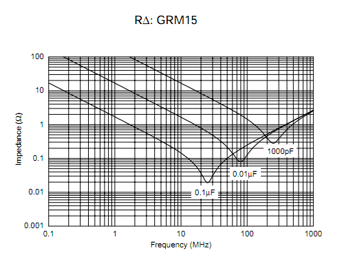
Based on the previous data, here is a table showing the approximate maximum frequency for bypass (decoupling) capacitor values:
Capacitor Value Frequency Max Table
Capacitor |
0.1 uF |
0.01 uF |
0.001 uF |
~Max Freq. |
25 MHz |
75 MHz |
115 MHz |
Back to Top
ESL & ESR For Different Package Footprint Sizes
Other factors being equal, ESL and ESR tend to be equivalent for different capacitor values given the same footprint package size:
The ESL and ESR is reduced in smaller footprint package sizes given the same capacitance value:
Capacitor Footprint Size Impedance Table (3)
Package |
ESL (pH) |
0201 |
400 |
0402 |
550 |
0603 |
700 |
0805 |
800 |
1206 |
1250 |
0612 |
63 |
Back to Top
Effective decoupling coverage can obtained by using smaller footprint packages for the smaller capacitor values to filter out the higher frequencies. The red line represents the approximate parallel capacitance impedance for the 1.0uF, 0.1uF, and 0.01uF capacitors in parallel:
Capacitor Types & General Properties
Capacitor Types & Attributes Table (3)
Type |
Cap Range |
ESR |
Voltage Rating |
Notes |
Ceramic |
uF to pF |
Low |
High |
Multipurpose,
Inexpensive |
Mica |
pF to nF |
Low
0.01 to 0.1
Ohms |
High |
Good for RF Filters, Expensive, Stable |
Plastic Film
(polyethylene
polystyrene) |
uF's |
Medium |
High |
Inexpensive, Low Freq. |
Tantalum |
uF's |
High
0.5 to 5.0
Ohms |
Lowest |
Expensive, Non-Linear, Not good for Audio |
Aluminum
Electrolytic |
High uF's |
High
0.05 to 2.0
Ohms |
Low |
Inexpensive, Low Freq. |
OSCON |
uF's |
Low
0.01 to 0.5
Ohms |
Low |
Expensive, Very High Quality |
Back to Top
General Capacitor Notes
- Long & thin PCB traces increase ESL & ESR. Bypass Caps should be placed as close as possible to the VDD pins of componants as possible, with as thick as possible traces.
- Smaller footprint package sizes result in lower ESL. The higher frequency bypass caps are best selected in smaller packages.
- Generally speaking, putting capacitors of the same value in parallel reduces the ESL and ESR of the combined set. The overall capacitance value will be increased, i.e. capacitors in parallel combine in the same way that resistors combine in series.
- Tantalum and Aluminum Electrolytic capacitors should have a voltage rating at least twice the voltage used in the circuit application. They are also polorized--they must be installed in the proper orientation during assembly. Tantalums are especially sensitive to this.
References
Back to Top
|